Building an AI Studio Feasibility Copilot for Vehicle Shape Exploration
Problem
Car design is full of tradeoffs.
A designer may want to make a vehicle longer, lower, wider, or more aggressive. An aerodynamics engineer may care about drag. A package engineer may care about whether the vehicle still fits realistic layout constraints. In real automotive development, those questions are answered through a mix of CAD reviews, simulation, engineering judgment, and many rounds of iteration.
For this project, I wanted to build a small version of that workflow.
The goal was not to replace CAD tools, CFD simulation, or studio engineering expertise. Instead, the goal was to explore a practical question:
Can we build a lightweight AI tool that lets someone change vehicle geometry parameters, estimate the aerodynamic impact, and flag whether the design change still looks plausible?
I started from an open automotive aerodynamics dataset, used a machine-learning model to predict drag coefficient, and combines that prediction with simple rule-based checks. The user can select a baseline vehicle run, adjust geometry parameters, and immediately see whether the change appears promising, risky, or infeasible.
Simply put it's designed to answer questions like:
“If I make this vehicle concept shorter, wider, or lower, what happens to predicted drag and does the change still look reasonable?”
This project is intentionally scoped as an educational project. The feasibility checks are heuristic, not official OEM package rules. The geometry parameters come from a public research dataset, not production vehicle data. But the workflow is designed to reflect an important idea: AI-generated or AI-assisted design is only useful when it is paired with engineering constraints and clear decision support.
Modeling
The modeling task is straightforward:
Use vehicle geometry to predict aerodynamic drag.
More specifically, the model predicts Cd, or drag coefficient, from geometry-only inputs. This matters because the app is meant to answer design-time questions. If a user changes the vehicle length, width, height, ride height, or pitch, the model should be able to estimate the aerodynamic impact without needing a completed CFD simulation first.
That design choice shaped the feature set. I intentionally excluded simulation outputs such as force columns, lift coefficient, side-force coefficient, and other post-run aerodynamic values from the model inputs. Those values may be useful for analysis, but they would not be available when a designer is experimenting with a new geometry. Including them would make the model look better on paper while making it less useful in the actual workflow.
The training table contains 484 labeled vehicle-geometry rows after dropping rows with missing Cd values. After feature construction, the model uses 25 input columns. These include the raw DrivAerML-style geometry parameters and a small set of engineered proxy features.
The raw geometry inputs include parameters such as:
vehicle length
vehicle width
vehicle height
front and rear overhang
hood angle
windscreen angle
rear diffuser angle
rear-end tapering
greenhouse tapering
ride height
vehicle pitch
On top of the raw parameters, I added engineered features that make the geometry easier for the model to reason about. These include:
length_to_width
height_to_width
wheelbase_proxy
wheelbase_to_length
frontal_area_proxy
overhang_total_proxy
overhang_front_proxy
overhang_rear_proxy
These are not perfect engineering measurements. They are practical proxies built from the available open dataset columns. This is was an attempt of using the data honestly, making the assumptions visible, and not pretending this is a production OEM package model, far from it.
For the model itself, I compared three approaches:
Model | Purpose |
|---|---|
Mean baseline | A sanity check that always predicts the average Cd |
Ridge regression | A simple linear baseline |
XGBoost regressor | The main nonlinear surrogate model |
The XGBoost model uses 500 estimators, shallow trees, a low learning rate, subsampling, column sampling, and L2 regularization. Simply put, it is a controlled gradient-boosted tree model that can learn nonlinear relationships in tabular data without requiring a huge dataset.
This motivated why XGBoost was a good fit for the first version of the project. The input is not a raw 3D mesh or image. It is structured vehicle-geometry data. For that kind of tabular problem, a strong tree-based model is often a better first choice than jumping straight to a neural network.
Model Results Analysis
The model was evaluated on a single 80/20 train/test split. The goal was not only to get a good score, but to check whether the surrogate was accurate enough to support early directional design exploration.
Model | MAE | RMSE | R² |
|---|---|---|---|
Mean baseline | 0.01384 | 0.01708 | -0.025 |
Ridge regression | 0.00465 | 0.00602 | 0.873 |
XGBoost | 0.00382 | 0.00459 | 0.926 |
The mean model performs poorly, which is expected. It does not use geometry at all. Ridge regression performs surprisingly well, which tells us that a large portion of the drag signal is already captured by relatively smooth relationships in the geometry parameters.
XGBoost improves on Ridge and becomes the surrogate model of choice here. Its hold-out R² of 0.926 suggests that the geometry features explain most of the variation in Cd across the test set. Its MAE of 0.00382 Cd means that, on average, predictions are off by less than four-thousandths of a drag coefficient point.
That does not mean the model replaces CFD. It means the model is useful as a fast directional estimator.
A good way to read the result is:
If the user makes a modest geometry change near the training distribution, the model can give a useful early estimate of whether Cd is likely to move up or down.
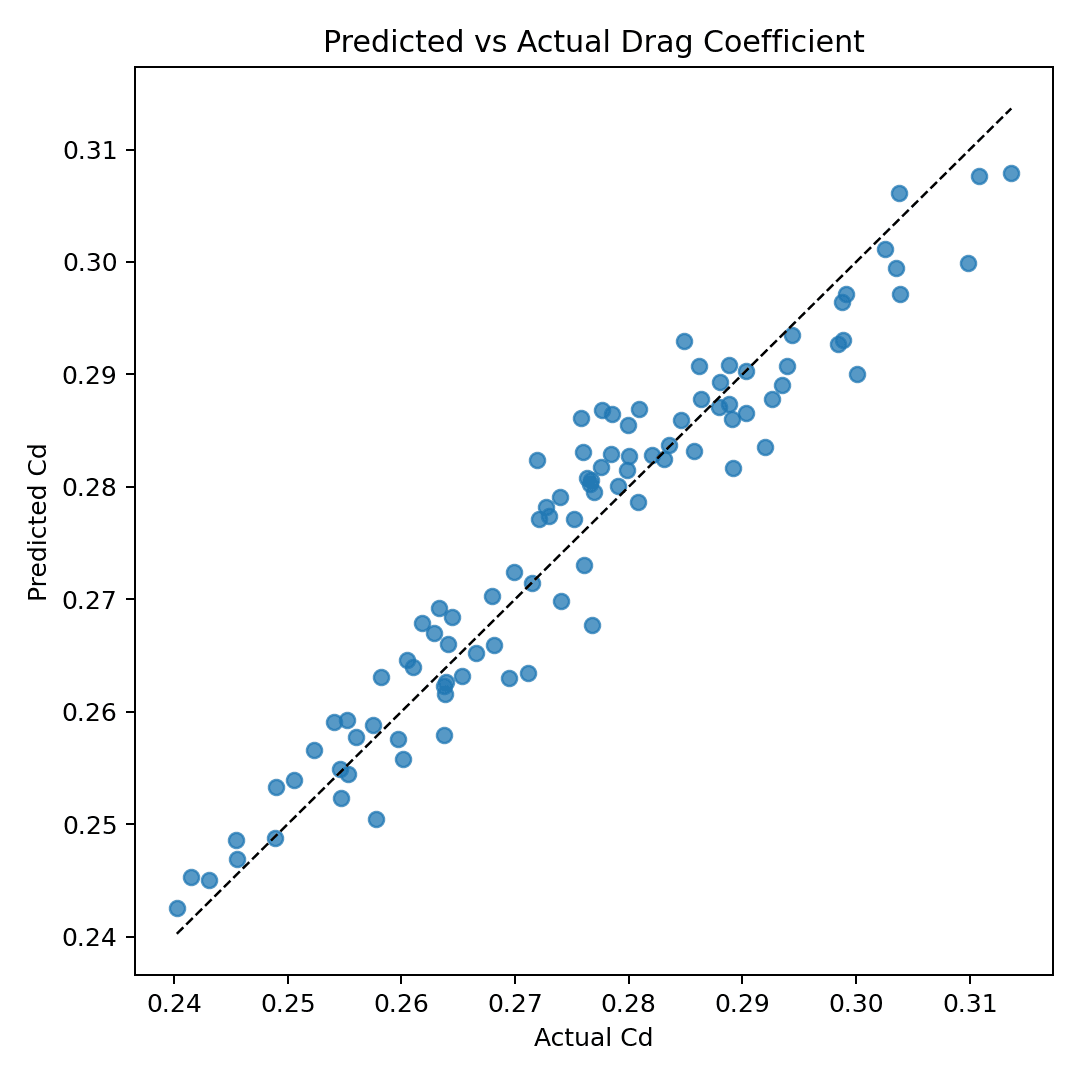
The below predicted-vs-actual plot supports this. Most points fall close to the diagonal reference line, which means the model’s predictions generally track the true Cd values from the dataset. There is still scatter, especially near the high-Cd end, but the overall calibration is strong enough for a design-exploration.
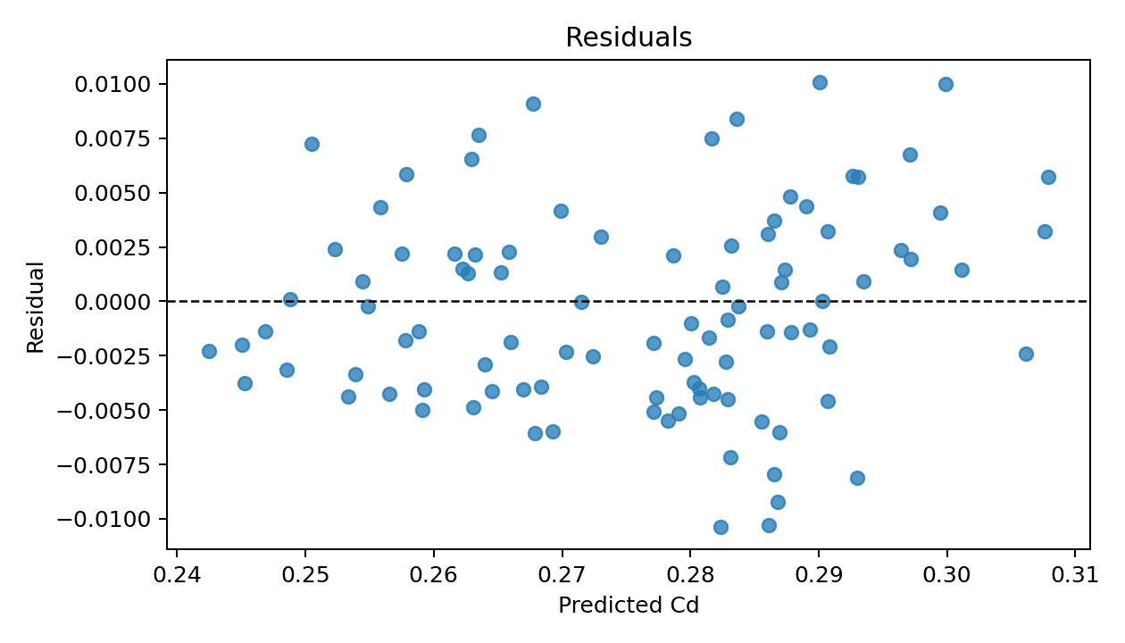
The following residual plot gives a second view of model quality. Residuals are centered around zero, which is a good sign: the model is not obviously overpredicting or underpredicting across the entire test set. There are some errors around ±0.01 Cd, so I am not presenting the predictions as exact.
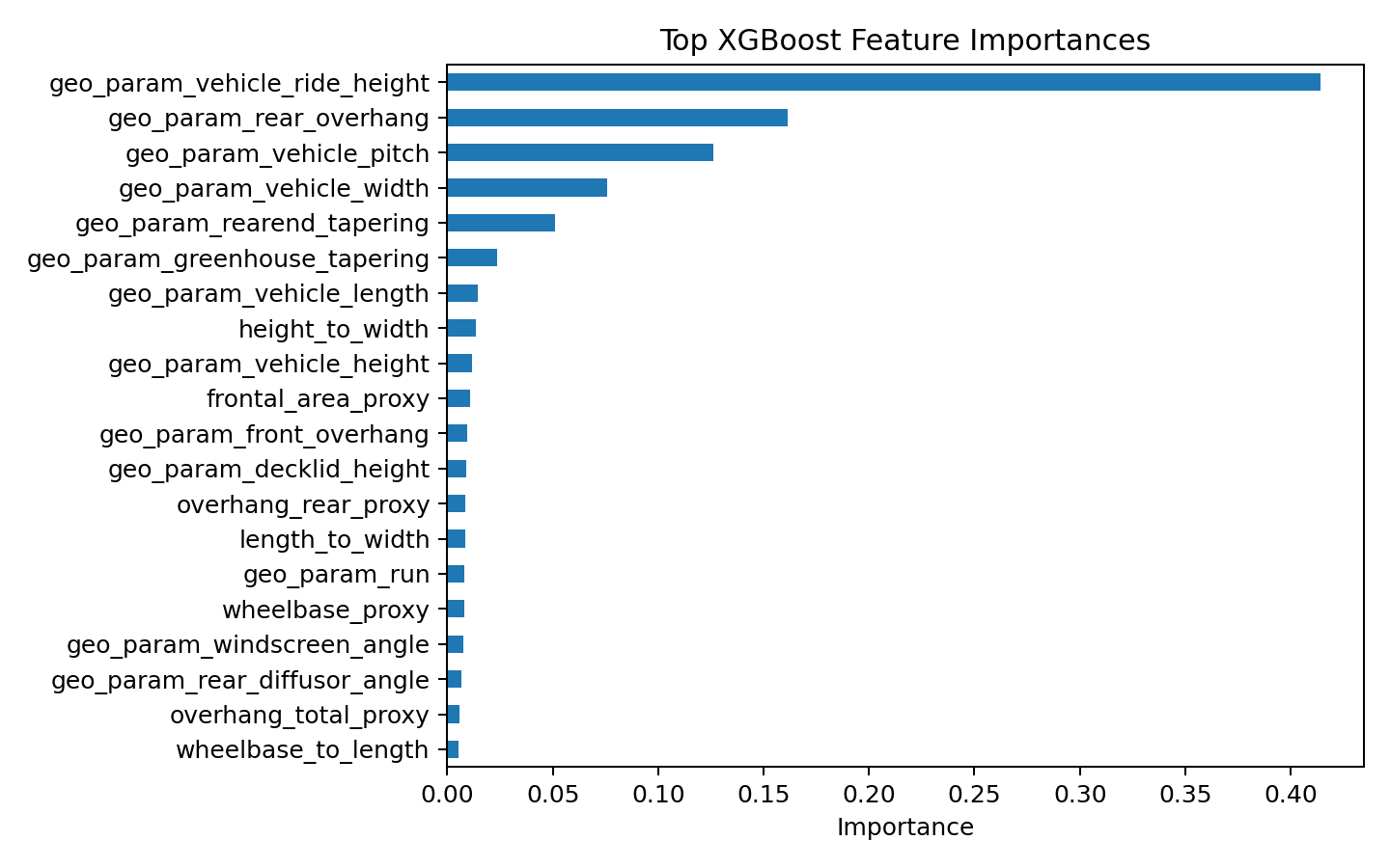
The next feature-importance plot shows that the model relies most heavily on a small number of geometry parameters. The strongest feature is geo_param_vehicle_ride_height, followed by geo_param_rear_overhang, geo_param_vehicle_pitch, geo_param_vehicle_width, and geo_param_rearend_tapering.
That result is useful from a storytelling perspective. The model is not treating every variable equally. It has learned that certain geometric choices have much more influence on predicted drag than others.
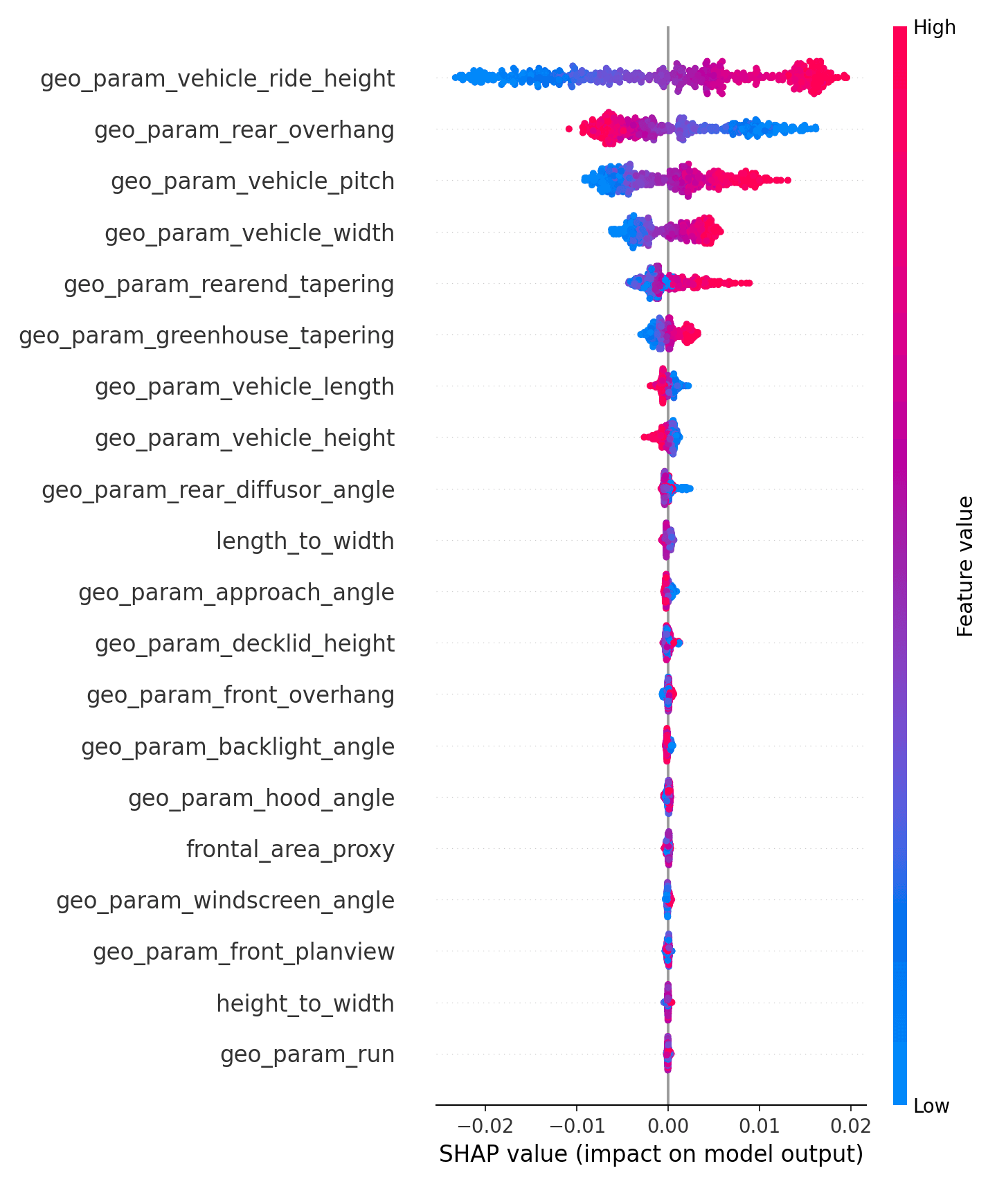
Lastly, I also used SHAP values to inspect the direction and spread of feature effects. The SHAP summary plot is especially helpful because it shows not only which features matter, but how high or low feature values tend to push the prediction.
For example, the SHAP plot shows large effects from ride height, rear overhang, pitch, width, and rear-end tapering.
High level take away from modeling analysis:
The XGBoost surrogate is accurate enough for a lightweight design-exploration demo, especially when paired with feasibility checks, out-of-distribution warnings.
Raw prediction is not enough, we needs to show whether the geometry change is plausible, whether it stays near the training data, and which rules or features explain the result.
That is why the final system combines three pieces:
predicted Cd + heuristic feasibility checks + explanation layer
The model estimates aerodynamic direction. The rules layer keeps the design from drifting into obviously unrealistic geometry. The explanation layer helps the user understand why the app gave that recommendation.
Front End Demo App and Examples

The front end is designed as a small interactive design sandbox.
The user starts by selecting one of several demo vehicle runs from the dataset. For each run, the app shows the baseline geometry parameters, the known dataset Cd, the model-predicted Cd, and a visual preview of the vehicle geometry.
From there, the user can edit geometry parameters and evaluate the proposed design change.
A typical interaction looks like this:
Select a baseline run.
Change a geometry parameter, such as vehicle length or height.
Click evaluate.
See the new predicted Cd.
Review whether the design passes, warns, or fails the heuristic feasibility checks.
Inspect which parameters changed and which rules were triggered
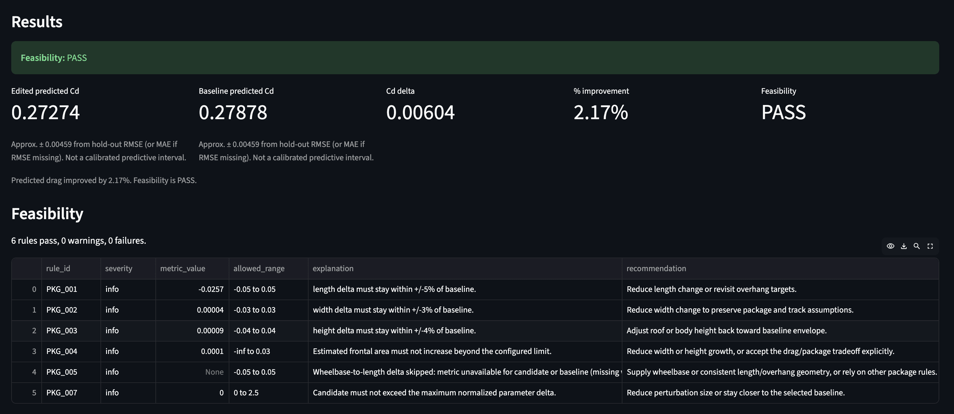
For example, a user might ask:
“What if I reduce the vehicle length by 2.5% , reduce Rear overhang by 15.6%?”
The app then returns a result like:
Or the user might try a more aggressive change:
“What if I increase the vehicle length by 25% , reduce Rear overhang by 25%?”
Then results would show:
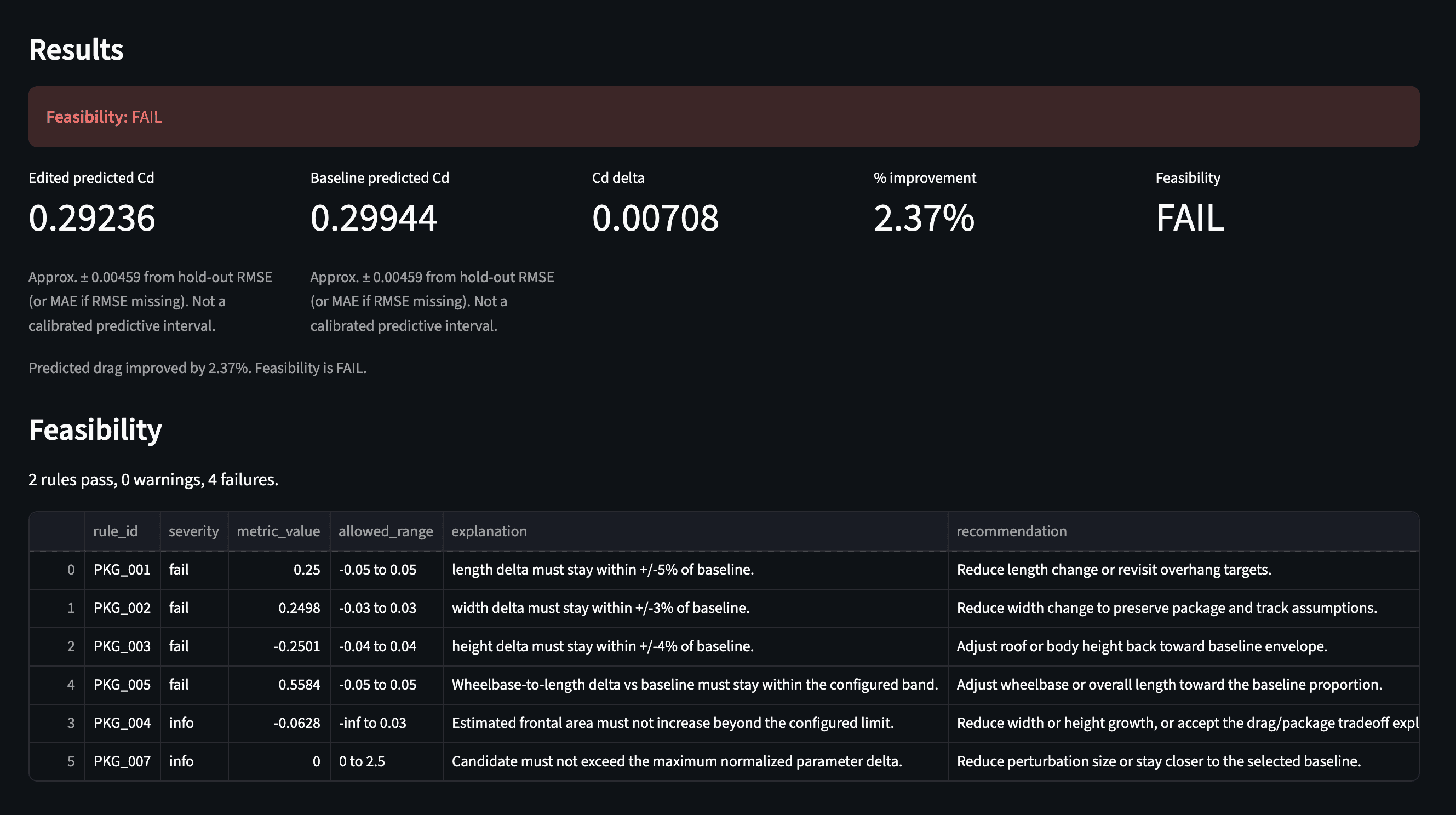
In this case, the model might predict a lower Cd, but the rules layer flagged the design as infeasible.
A machine-learning model by itself might say, “This version has lower drag.” But a studio-feasibility copilot should also ask, “Does this still look like a plausible vehicle concept?”
For this demo I included rule checks such as:
length change relative to baseline
width change relative to baseline
height change relative to baseline
estimated frontal-area drift
parameter range checks
out-of-distribution warnings
These checks are intentionally simple and transparent. Each rule returns a severity, measured value, allowed range, explanation, and recommendation. That makes the output easier to understand than a single numeric score.
What I Learned
This project helped me connect ML engineering with automotive design and studio engineering.
The most interesting part was not just predicting drag but building the surrounding workflow:
prediction + feasibility + explanation + traceability
That combination is what I think makes an AI tool more useful for engineering design.
A raw model score is not enough. A useful copilot needs to help the user understand:
what changed
what improved
what got worse
what constraints were triggered
whether the prediction is trustworthy
In future versions, this project could be extended with larger datasets, richer geometry representations, point-cloud modeling, more realistic package constraints, better 3D visualization, and integration with CAD-style scaffold exports.
But even in this first humble version, the project demonstrates a practical idea:
AI can support early vehicle design exploration, but it becomes much more valuable when it is grounded in geometry, constraints, and clear engineering feedback.